First off, thank you so much everyone for your amazing initial response! We hit our funding goal within half an hour of campaign launch!
Over the next few weeks, we’ll be releasing a series of updates showcasing particular aspects of Tangara’s design. The first of these is written by Daniel (@ailurux), and will cover a feature many of you have been curious about: the touchwheel
In this update, we’ll go through the history of why we chose a capacitive touchwheel for Tangara, how the current design works, and what it can do, as well as some resources and tips for incorporating this kind of touchwheel into your own projects.
To Begin, a Bit of Background…
Tangara’s input hardware has changed a lot over the last year of development. Whilst Tangara’s current design may be nostalgic for fans of the original iPod, our original concepts were actually much more inspired by cassette tapes. I’ve long had an affinity for cassette tapes, and there is some overlap between my love of tapes and my excitement about making a physical, distraction-free music player that can’t suddenly decide you don’t have the right to listen to your music.
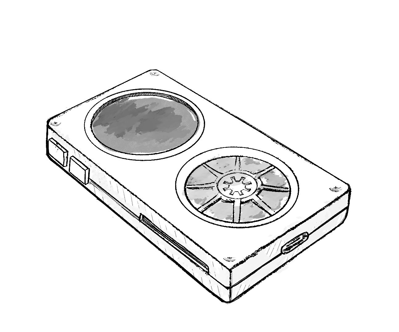
The notion of using a circular screen was short-lived. Whilst it’s absolutely possible, and circular TFT screens are available and fairly cheap, it just wasn’t functional to reduce the screen real-estate by about a fifth just for the aesthetics. But already, a wheel was feeling like a compelling input method.
We made a few prototypes that used a rotary encoder with a 3D printed wheel or knob, but we realised this method was going to add a lot of complexity and bulk to the case, especially if we wanted a push-button as well.
Our next idea was to use an angular sensor, as they have a lower profile and can detect position as well as rotation. However, these components don’t come with push buttons, often don’t have a full 360 degree operating angle, and still required a separate part – one with even tighter tolerances.
With neither of those two initial ideas working, we went back to the drawing board and came up with a bunch of different ideas. We had a pretty good idea of what our requirements for the input were at this point: we wanted something low-profile, affordable, with some kind of haptic or tactile feedback, and with enough flexibility to support multiple methods of use.
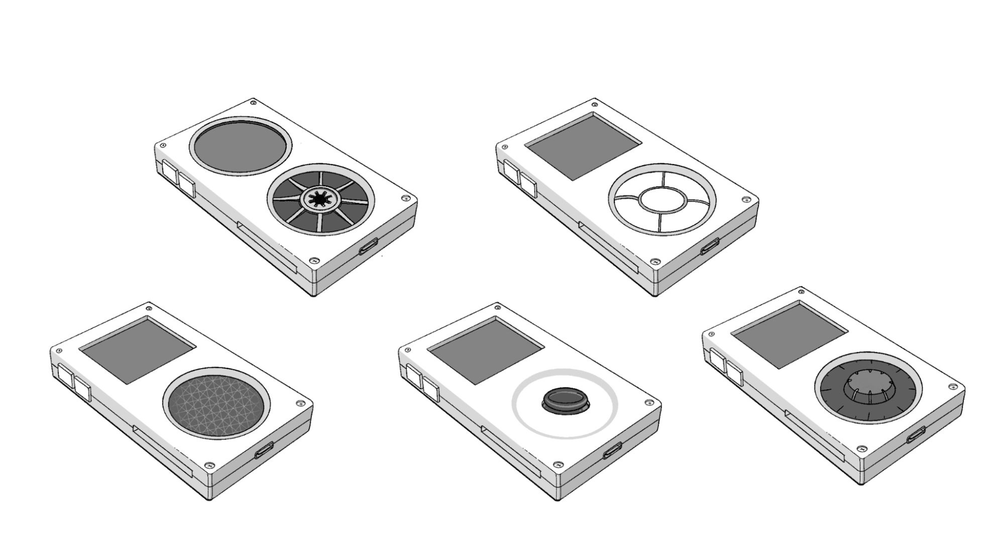
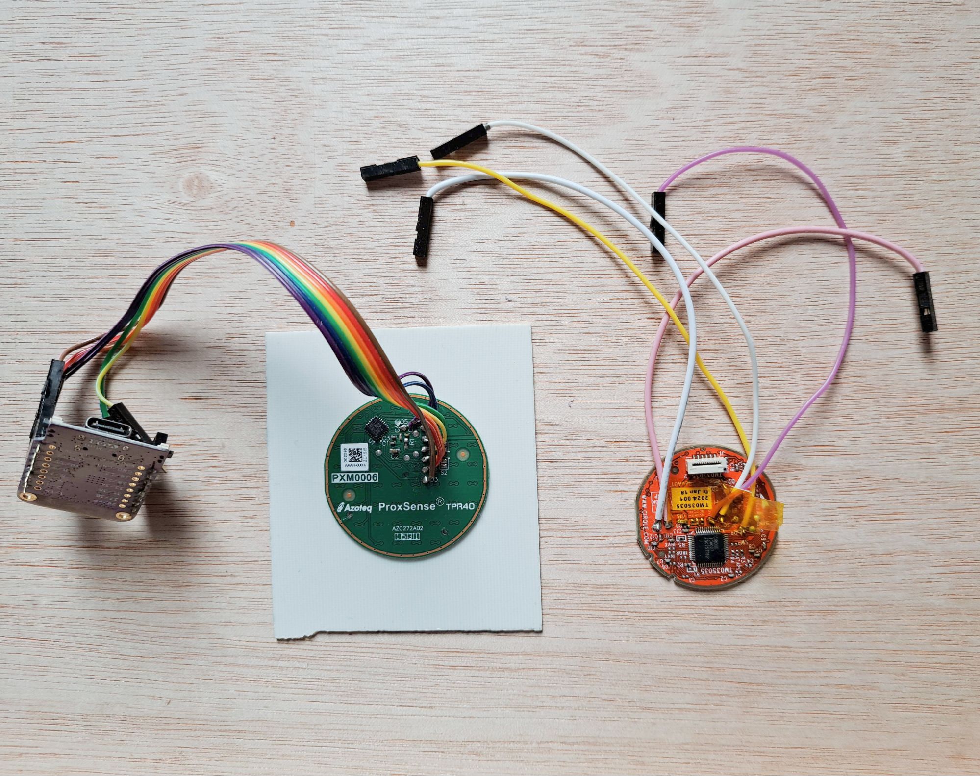
The most promising idea was to use a circular trackpad module, like the Azoteq ProxSense or Cirque Glidepoint trackpads. These are very low profile, high resolution trackpads that come in a variety of sizes and seemed ideal. We ordered a few of these modules and built some prototypes to test. Unfortunately, we discovered the Azoteq ProxSense range requires an additional, rather-costly flashing tool (and Windows-only software) to unlock its full functionality, with only basic gesture controls available by default. Our prototypes with the Cirque Glidepoint trackpad worked better, but we were worried about the cost and availability of these modules for smaller manufacturing runs.
We then considered designing and manufacturing our own custom trackpad module for Tangara. Whilst researching this, we found a design guide on capacitive touch sensors that described a wheel sensor design for capacitive touch electrodes. This design would allow us to build a capacitive touchwheel directly onto Tangara’s faceplate. Not only would we be able to do this with just one affordable IC and three fancy-shaped electrodes, but it would also be extremely low profile, give us the flexibility to customise the size and shape, and even leave us room for a middle button and haptic motor. We were really excited by this and so we set to the task of making a prototype.
How (Not) to Re-Invent the Wheel
The aforementioned design guide is a really great resource on how this kind of capacitive touch wheel works, and I’d highly recommend starting there. The guide lists a few different arrangements of electrodes for different capacitive buttons, sliders and wheels.
One way to make a capacitive touch wheel is to place many electrodes in order in a circular arrangement and when one of these electrodes detects a touch, based on the known order of electrodes the approximate position of the finger on the wheel can be determined. This is actually how the iPod’s click-wheel works.
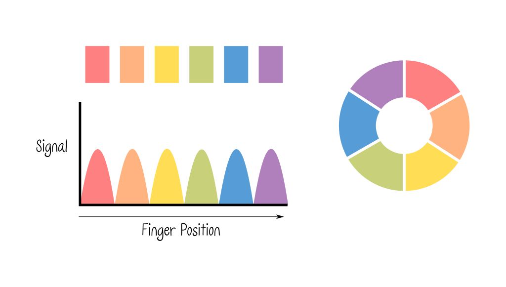
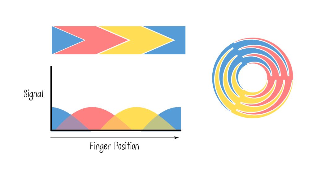
Another way is to use just three electrodes with an interpolated shape, so that as the finger moves around the sensor, the signal moves smoothly between electrodes and we can use this to determine roughly where the finger is on the wheel.
We were pretty excited to try out the interpolated wheel design, the only thing left was to figure out how to create that tessellating, radial zig-zag shape. I watched Jacqueline try to trace the image from the design guide in KiCad, manually clicking each point along the path for 15 minutes or so, when a misclick caused the path to be lost and she paused for a moment, sighed, and then started over again. I felt a need to jump in at this point and said I’d create the path as an SVG and send it to her.
I knew I wanted to programmatically create this shape, with the ability to tweak the parameters so that we could quickly iterate on the design if needed. I’ve previously used JavaScript to generate SVG files, so I reached for that here.
I found this decade old blog post which was really helpful. It details how the author solved this problem with OpenSCAD by using chain-hulls in place of arbitrarily defined paths. As SVG does allow for arbitrarily defined paths, I could use the author’s first idea of generating a triangular path around an arc.
The basic process is to generate the shape using polar coordinates, which, instead of defining a position from the origin in terms of X and Y, defines a point by its distance and angle from the origin. This allows us to move outward from the center in an arc, and we can switch the direction by changing the angle or draw a straight line outwards by changing just the distance.
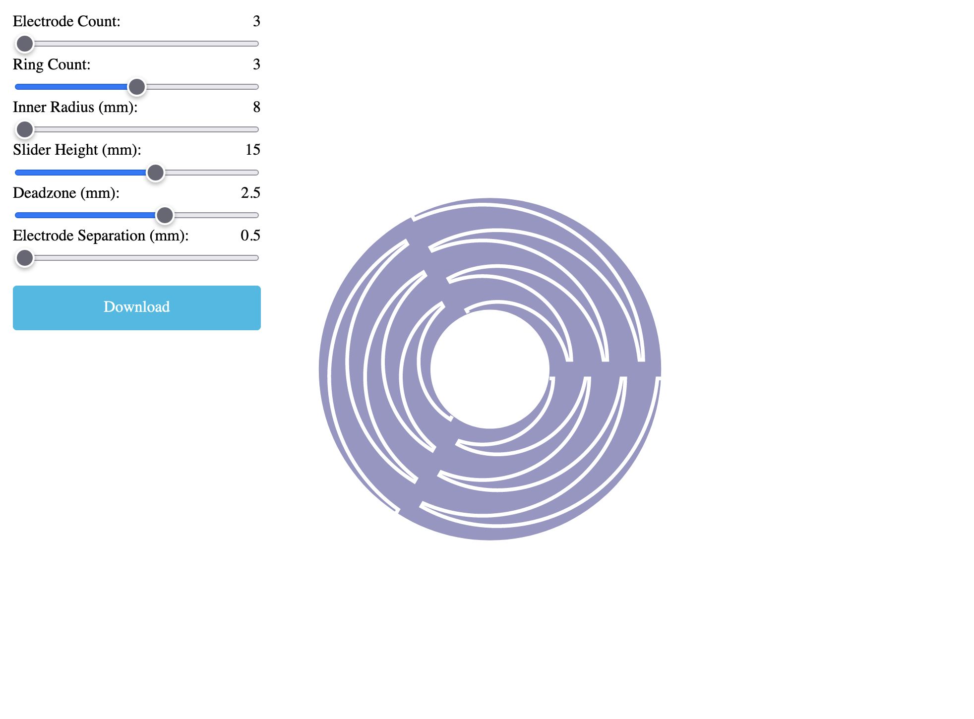
You can access our SVG tool here, along with the code that powers it, all of which is visible in the page source. The SVG path does usually need some manual processing before it can be used in a PCB, but this should hopefully be a good starting point for anyone looking to incorporate this kind of touch sensor into their own projects. I think it would be really cool to see more projects using it!
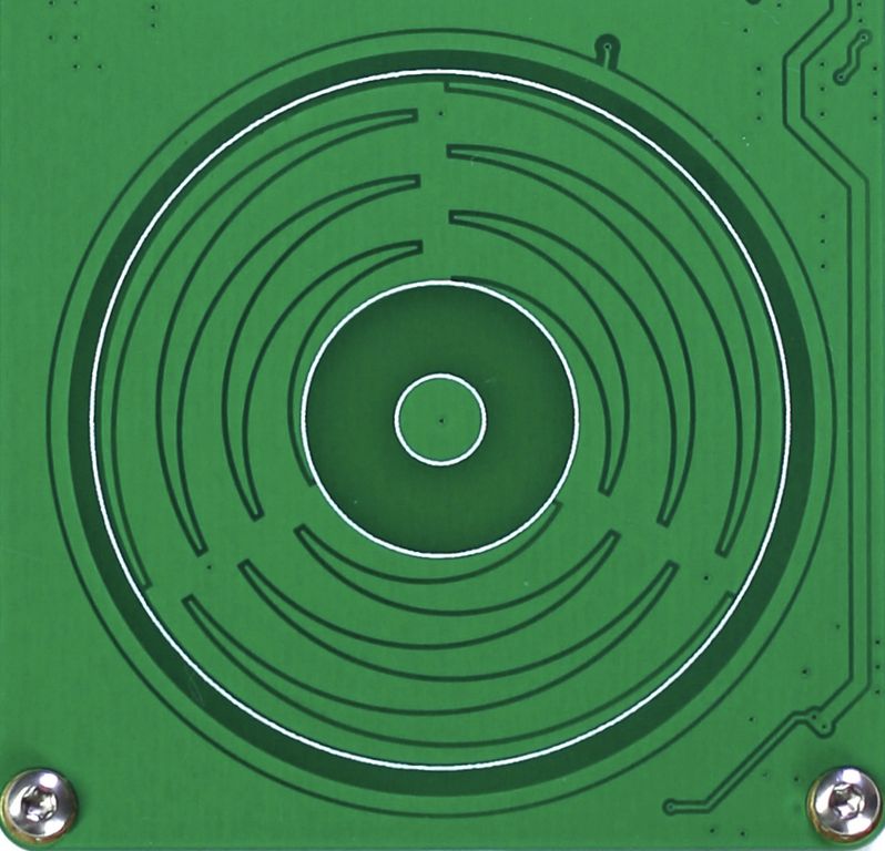
We were super-impressed with the performance of the final result. With just three electrodes and a cool form-meets-function design, we’re able to offer a touch input that feels really responsive and nice to use. This design can also support other input methods, such as a directional pad mode, or even just using the wheel as a large button. We’ve even experimented with using the angular detection to control the pitch of a basic square wave synthesizer, which produced fun results.
Final Thoughts
Overall, we’re really happy about what we’ve come up with for Tangara’s input. It’s space-efficient, versatile, and effective. We think the touchwheel is a great fit for this kind of device, but because we’ve implemented it on a separate PCB, it’s also easy to replace with other input hardware. In a later update, Jacqueline will be showing off a custom faceplate featuring a rotary encoder and buttons.
Meanwhile, there’s still plenty of time to support our campaign!